Updated and Improved VCO
As the name implies I have finally gotten around to improving and re-laying out the VCO. Notice that the input impedance of the CV inputs has been changed to 49.9K. This is to accomodate the 1K PRC PT146 Temperature Compensator. If you buy a 2K PT146 Temperature Compensator then go back to using 100K 1% resistors for R2, R5, R7 and R11. Input scaling will be 1V/Octave in either case. This circuit uses modern, easily accessible parts (You can sub a National LM13600 or Phillips NE5517/A if you don't have an LM13700). The MPF102 can be replaced with a 2N5457. I have faith that you will be satisfied with the performance of this oscillator. You should read the whole page so you get all the little notes and any explanations of changes.
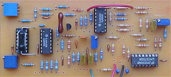
Use 1% metal film resistors anywhere the frequency will be effected by temp drift. You can use 5% carbons elsewhere. On my circuit (pictured below) the metal films are blue and the carbons are beige if you want a guide. When in doubt use 1% metal film. Use a good capacitor for the integrator (C4). Mica or Polystyrene will work nicely and will minimize temperature effects. You can add more 49.9K CV inputs if you want. You will notice that the glitch reduction cap is gone. It was more trouble than it was worth. I don't think a bat could hear the glitch frequency. Since the wave shaping OP-Amp includes the comparator for the square wave you will notice some effect on the ramp and triangle waves (again the freq content of the contribution is out of the normal range of human hearing). This oscillator is for audio range and you will notice that the glitches affect the waveforms more as the frequency gets closer to 18 to 20 kHz. You can kludge a 560 pF cap across R27 to reduce some of the glitching that occurs in the ramp to triangle convertor.
Remember to mount the PT146 in contact with the CA3046 package (as shown at the bottom of this page). This temperature compensator (which is not exactly a TelLabs Q81 but is very close) will keep the frequency more stable with temperature changes. I put heat sink compound between the CA3046 and the PT146 for better thermal matching. You can use two matched transistors if you desire (thats the reason for the extra pad at pin3 of IC4) but observe that you insert them into the board correctly.
You would insert them like so:
Pad for pin 1 IC4 - Collector of matched transistor 1
Pad for pin 2 IC4 - Base of matched transistor 1
Pad for pin 3 IC4 - Emmitter of matched transistor 1
Pad for pin 3 IC4 - Emmitter of matched transistor 2
Pad for pin 4 IC4 - Base of matched transistor 2
Pad for pin 5 IC4 - Collector of matched transistor 2
Depending on how siney you like your sine wave you may want to change the value of R15. Making it's value somewhat higher will reduce the sinization (how's that for a word) imposed by the LM13700 circuit. Making it somewhat lower will have the opposite effect. You probably want to stay within plus or minus 10K.
This circuit will probably work fine with + and - 15 volts too.
Inputs and Outputs
- cv-in (1V/Octave control voltage inputs)
- SO (Sync out)
- sin (Sine Wave out)
- tri (Triangle Wave out)
- snc (Sync input)
- saw (Sawtooth wave out)
- sqr (Square/Pulse wave out)
- pw (Pulse width modulation input)
- Lin CV (Linear response control voltage input)
Updated and Improved VCO
Updated and Improved VCO Panel Coarse and Fine Tuning Hookup
VCO Calibration Tool
Calibration of the circuit is easy. Adjust the Coarse and Fine tuning so that you have 1KHZ at point RW (Ramp Wave). Adjust R47 until you see a triangular waveform at tri. The triangle wave rectifier only works when the ramp wave appearing at pin 14 of IC3-D is oscillating about ground (half of the wave above ground and half of the wave below ground). Increase the scope's vertical gain and observe the bottoms of the triangle waves. Adjust R47 until the descending ramps meets the ascending ramps. Next adjust R43 so that the sine output (circuit point sin) has symmetrical sinusoidal characteristics on top and bottom. The sine wave should sound pure. You will notice that when you adjust the offset so that the waveform goes either too high or too low (and thus becomes distorted) that the octave harmonic will begin to be emphasized. So use your ears to determine when the sine is distortion free enough for you.To adjust the scale of the oscillator I recommend that you permanently breadboard the following circuit together because you will use it time and time again. After it is built and calibrated as described connect its output (pin 7 of IC1-B) to one of the cv-ins of the VCO. Start at the ground setting (S1 set so that pin 9 is connected to its pin 1) and then select each selection in turn. Keep going forwards and backwards as you simultaneously adjust the VCO's scale trimmer. Adjust the trimmer until you get an octave change in frequency each time you advance the selector. If you notice that at very high frequencies the oscillator tends to be flat then adjust trimmer R14 to boost (slightly raise) the high frequencies. I found that this oscillator tracked pretty well and I look forward to building a bank of them for my synth. This circuit works (I built and tested one) so if you are having problems see my trouble shooting page for help.
I have changed the integration capacitor to 330 pF but you can experiment with between 330 pF and 2000 pF to get the most trackable range. The original .02uF is a bit large for the MPF102 to discharge quickly (it works but a smaller cap is better for high frequency tracking).
Updated and Improved VCO PCB Layout (Component Side View)
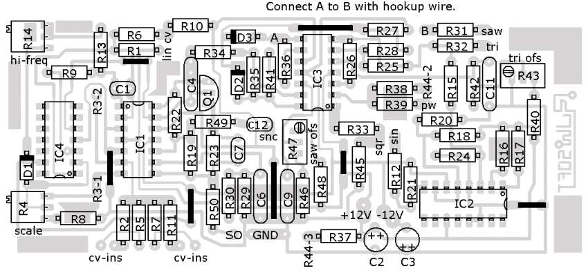
Updated and Improved VCO Parts Placement
Updated and Improved VCO Picture
Updated and Improved VCO FacePlate PDF
Click image to download PDF